Protecting Enterprise Remote Desktop Services with SafeNet Trusted Access
Overview
This guide primarily documents the procedure for protecting Remote Desktop Services (RDS) through native enforcement in the Remote Desktop Gateway (RDGW) extending Network Policy Server (NPS) RADIUS to SafeNet Trusted Access (STA) and authenticating the requesting user with Push Authentication to MobilePASS+. Secondarily, this guide also documents an alternative architecture where instead of RADIUS, a SafeNet agent is deployed co-located with NPS to facilitate agent-based authentication with SafeNet Trusted Access over encrypted tunnel (TLS 1.2 over 443). Related to this, a proposed High Availability (HA) architecture is documented as well. Lastly, the guide briefly expands on troubleshooting tools and procedures related to deployment.
Note
This guide documents alternative deployment architectures. These do not replace SafeNet official deployment architectures using RDWeb and RDGW agents (see Support Portal of downloads and documentation of said agents).
Prerequisites
RDGW is configured and published with valid public certificates
RDGW Resource Authorization Policy (RD RAP) is configured to allow access to required resources
NPS role is installed for RDGW Connection Authorization Policy (RD CAP)
Auth Node for the RDGW server is configured in STA
A user with a MobilePASS+ authenticator is enrolled
Solution Architecture
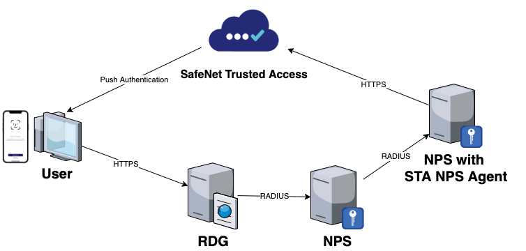
The high level target architecture is shown below. The user requests a remote desktop service and inputs their username and domain password. The access-request is intercepted by RDGW policy and forwarded to SafeNet Trusted Access (STA) over RADIUS (UDP 1812) via Microsoft NPS. STA then sends an OTP Push notification to the requesting user’s mobile device. The user approves the push request and is authorized to the remote desktop service.

Note
Please see Appendix A for additional deployment options, using an on-premise NPS server with STA NPS Agent installed
Step 1: Configure STA Auth Node for RDGW
To be able to use RDGW with STA RADIUS, an Auth Node has to be created with the Public IP of the RDG server. To do so:
Open STA (MFA Management Console)
Navigate to Comms tab
Scroll down to Auth Nodes and click on Auth Nodes
Click Add to add a new Auth Node:
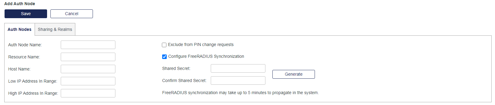
In Auth Node Name, type in any name for this Auth Node, for example RD Gateway
In Low IP Address in Range, type in the Public IP of your RDG server
In Configure FreeRADIUS Synchronization – Shared Secret, type in a Shared Secret or click Generate to generate a random one (copy and save the shared secret to be used in step 2.9)
Click Save to save the newly created Auth Node
Step 2: Configure RD CAP policy
RD CAP configuration will create all the required policies in the local NPS server to allow forwarding of the RADIUS requests to the STA Cloud RADIUS. To do so:
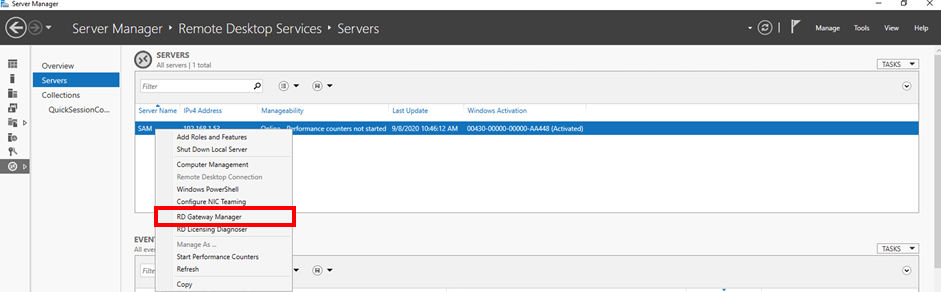
Open Server Manager and click on Remote Desktop Services
In the Remote Desktop Services, click on Servers
Right-click your server and select RD Gateway Manager:
In the RD Gateway Manager, right-click on the server name and expand Policies
Click on Central Network Policy Servers
Click on Configure Central RD CAP, server properties opens, click on RD CAP Store:

Select Central server running NPS
Type in the RADIUS server FQDN or IP (see reference below) in the Enter a name or IP address for the server running NPS: field and click Add
Note
Depending on your service zone select the appropriate FQDN or IP address (FQDN is preferred):
SafeNet Trusted Access Service Zone |
FQDN |
IP Address |
|---|---|---|
EU Service Zone |
radius1.eu.safenetid.com
radius2.eu.safenetid.com
|
52.47.114.37
52.47.42.111
|
US Service Zone |
radius1.us.safenetid.com
|
35.196.203.247
|
Classic Service Zone |
radius1.safenet-inc.com
radius2.safenet-inc.com
|
109.73.120.148
69.20.230.201
|
Type in your Shared Secret (same Shared Secret configured in STA Auth Node in step 1.7) in the Enter a new shared secret: field and click OK
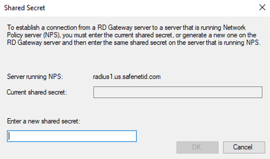
Click Apply and OK to save the RD CAP settings
Step 3: Adjust NPS Policies and Settings
The configuration of the RD CAP Policy creates the necessary policies and settings in NPS, those policies and settings need to be adjusted to allow Push Authentication to work correctly. To do so:
Open NPS and expand RADIUS Clients and Servers
Click on Remote RADIUS Server
A policy named TS GATEWAY SERVER GROUP will be available (created by RD CAP)
Double-click to open the policy
Select the RADIUS server (created by RD CAP) and click on Edit, the Edit RADIUS Server window opens
Click on Load Balancing
Adjust the value of: Number of seconds without response before request is considered dropped: and Number of seconds between requests when the server is identified as unavailable: to 60 (to allow enough time for the Push Authentication to complete):
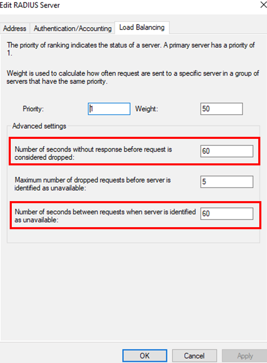
Click OK to save the timeout settings and Apply and OK to save the RADIUS Server settings
Expand Policies and click on Connection Request Policies
A policy named TS GATEWAY AUTHORIZATION POLICY will be available (created by RD CAP)
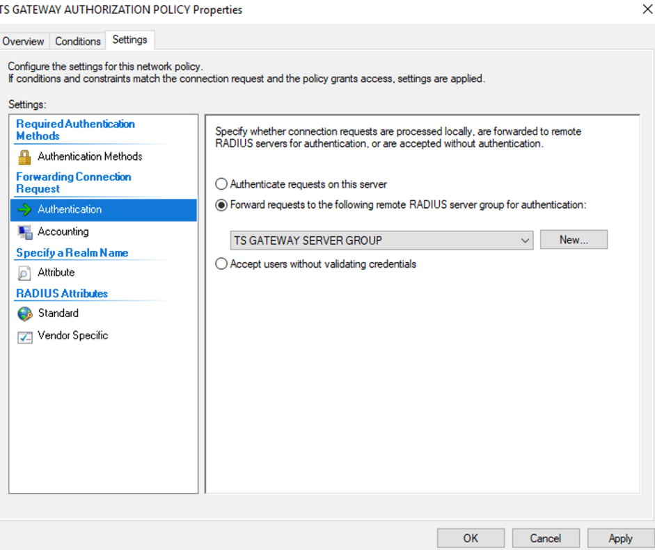
Double click to open the policy
Click on Conditions and adjust the conditions based on the company needs (for example Group Membership or Date and Time restrictions)
Click on Settings and click on Authentication, verify Forward requests to the following remote RADIUS server group for authentication: TS GATEWAY SERVER GROUP is selected:
Note
By default, RDG will send the username in DOMAINUser format, if STA user doesn’t have a username or an alias in the same format, the authentication will fail. To overcome this, UPN stripping is required, please see the steps below to configure attribute manipulation rule to adjust the username
Click on Attribute
Change the Attribute to be adjusted to User-Name
Click Add to add a new Attribute Manipulation Rule
In Find: filed type:
(.*)\\(.*)
and in Replace: field type
$2
Click OK to save the Attribute settings and Apply and OK to save the Connection Policy:

Click on Network Policies
Review and adjust the policy as required and then close NPS.
The RDG server side configurations are complete.
Step 4: Test the configuration
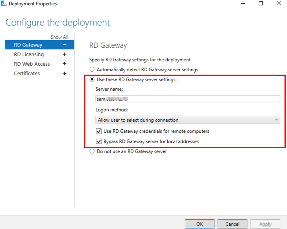
To test the configuration, adjust the RDP connection to use RD Gateway. The connection flow will first establish a connection to the RDG which will prompt the user to authenticate using domain username and password (if the credentials haven’t been saved yet) and send a Push Authentication to the user’s MobilePASS+ token, after successful Push Authentication, the user will be connected to the remote desktop. Depending on the RDP configuration, the user might be prompted for the credentials for the Remote Desktop or SSO can be used so the same credentials provided during the connection to RDG will be used for the Remote Desktop as well (Configured in Remote Desktop Services – Deployment Properties).
Open RDP (mstsc)
Click on Advanced
Under Connect from Anywhere click on Settings
Click on Use these RD Gateway server settings:
In Server Name, type in the FQDN of your RDG server
Adjust the Log-on method and Bypass RD Gateway server for local addresses as required:
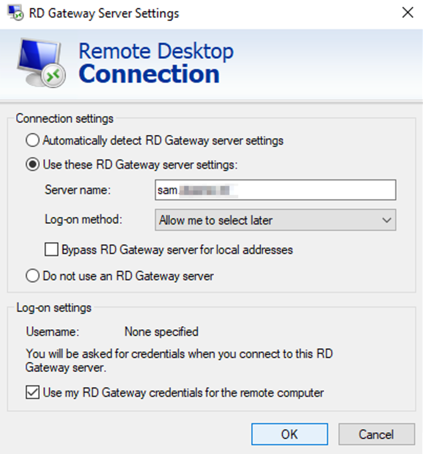
Click OK to save the settings
Click Connect to initiate the RDP connection through RD Gateway
The user is asked to provide the domain credentials (if the credentials haven’t been previously saved)

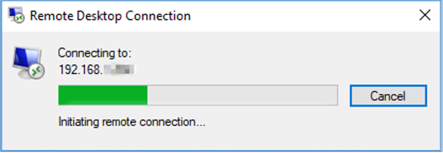
After providing the credentials, the connection initiates:
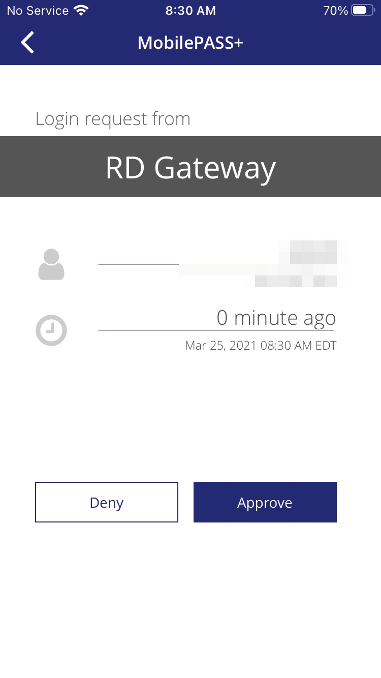
The user receives and approves the Push Authentication request:
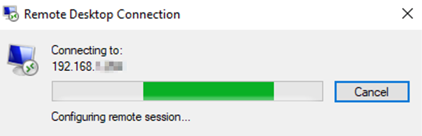
After approving the Push Authentication request, the connection is established:
Appendix A: Deployment Options
The deployment demonstrated in this guide is based on RADIUS communication between Microsoft Network Policy Server (NPS) and SafeNet Trusted Access (STA). Moreover, the suggested model uses a single NPS instance. It is also possible to deploy this solution using an additional NPS instance together with the SafeNet NPS Agent. In this deployment model, the RDGW NPS communicates locally to an additional NPS using RADIUS and acting as a client, and the STA NPS Agent then communicates to STA using HTTPS (443).
Note
The approach may be favorable when the first NPS instance is not allowed internet access or when RADIUS over the internet is not desired.
A high-level architecture of this alternative deployment model is shown below:
Note
Depending on your service zone select the appropriate FQDN or IP address to configure the STA NPS Agent (FQDN is preferred):
SafeNet Trusted Access Service Zone |
FQDN |
Port |
EU Service Zone |
cloud.eu.safenetid.com
|
443 |
US Service Zone |
cloud.us.safenetid.com
|
443 |
Classic Service Zone |
agent1.safenet-inc.com
agent2.safenet-inc.com
|
443 |
443 |
Appendix B: High Availability
Expanding on the deployment architecture shown in Appendix A, the below diagram shows a high-level architecture aimed at achieving redundancy or high availability in the solution. Here, components are mirrored to a second datacenter or zone and configured to communicate to two (2) RDG, NPS and so on. If one service is not available, another service is requested. High availability in SafeNet Trusted Access (STA) is ensured by the service provider (Thales) as long as the customer configures FQDN’s instead of IP address in directing traffic to the STA virtual server.

Appendix C: Troubleshooting
Test and Troubleshooting Tools
If possible, download the following tools to the servers involved in your RDGW and STA architecture:
NTRadPing - You can download NTRadPing here
Wireshark - You can download Wireshark here
Command Reference
The following commands are used from command line (CMD) to more rapidly recycle the NPS service :
Command |
Description |
Message |
net stop ias
|
Stop NPS Service |
The Network Policy Server service is stopping… The Network Policy Server service was stopped successfully. |
net start ias
|
Start NPS Service |
The Network Policy Server service is starting. The Network Policy Server service was started successfully. |
net stop ias && net start ias
|
Restart NPS Service |
The Network Policy Server service is stopping… The Network Policy Server service was stopped successfully. The Network Policy Server service is starting. The Network Policy Server service was started successfully. |
Common Issues
Missing or wrongly defined Auth Node
Whether you configure NPS to communicate directly to SafeNet Trusted Access (STA) over RADIUS (UDP 1812) or you employ the SafeNet Agent for NPS to communicate to STA over TLS (443) you must define an Auth Node in in the virtual server corresponding to the external IP address of your server. Verify that IP using an online tool such as https://www.whatsmyip.org/ or by executing the following command in command line (CMD)
curl ifconfig.me
Proxy impedes communication
Open a command line window (CMD) and execute the following command to learn if a proxy is present:
netsh winhttp show proxy
Set requests to inherit any proxy configuration from Internet Explorer settings:
netsh winhttp import proxy source = ie
Firewall impedes communication
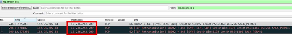
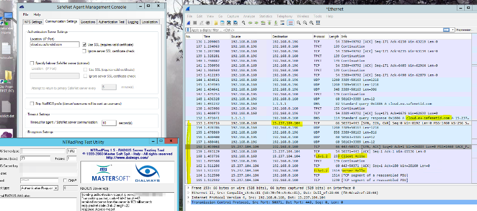
Install Wireshark (see above) and run a capture when attempting a connection.
To simplify: run the test using NTRadPing (see above) first and if it is successful only then move on to include actual components. A successful connection will appear as below. An unsuccessful connection will likely fail following resolving the STA FQDNs to IP addresses (follow TCP stream and it will show reconnection attempts):
Successful attempt:
Failed attempt: